 Optical network solutions
Containerized data centers,air or liquid-cooled.
Power distribution, cooling, IT racks, fire protection and monitoring, engineered into factory-built container modules for high-density computing. Each module is assembled, wired and tested before it ships, so the site only places, interconnects and commissions.
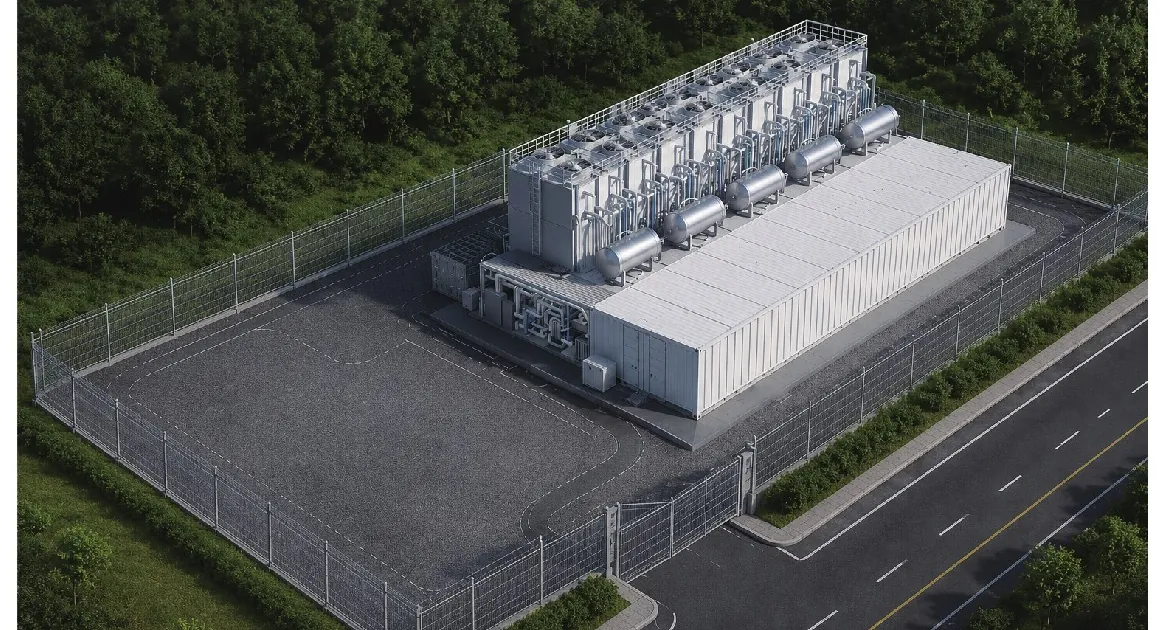
One container, or a multi-megawatt cluster.
Computing capacity that deploys quickly, relocates easily and grows module by module. Modules operate independently, so maintaining one never stops the others.
All-in-one
Power, cooling, IT equipment, monitoring and fire protection integrated in a single container: a self-contained data center in one module.
Functional modular
Dedicated containers for each function (IT, power, cooling, fire safety, monitoring and diesel generation) combined to match the site and the load.
Cluster deployment
Containers combine into standardized compute blocks. With 1.25 MW as the standard building block, capacity scales from 100 kW to beyond 10 MW.
Rapid deployment
Up to 60% faster than a traditional on-site build.
Modular expansion
Start with a single container; grow to multi-megawatt clusters.
Relocatable
Standard container form factor, easy to transport and redeploy.
Outdoor-ready
Built for harsh outdoor environments, from −40 °C to +55 °C.
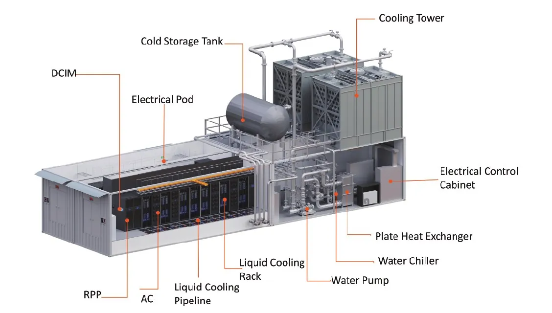
Oblique view: IT hall, electrical pod and cooling plant in one module.
System components
Every module ships with its services integrated:
- Cooling tower, cold storage tank, water chiller
- Plate heat exchanger and water pump
- Electrical pod and electrical control cabinet
- Liquid cooling racks and pipelines
- RPP (remote power panel) and precision AC
- DCIM monitoring
Configuration range.
IT capacity, cooling route, UPS topology, battery autonomy and power input are engineered to the site, the load profile and regional standards.
| Parameter | Configuration range |
|---|---|
| IT capacity | 100 kW – 10 MW+ |
| Rack quantity | 4 – 100+ racks |
| Rack power density | 10 kW – 150 kW+ per rack |
| Container type | Customized |
| Cooling technology | Air cooling / Liquid cooling / Hybrid cooling |
| Cooling capacity | 100 kW – 10 MW+ |
| Cooling method | Dry cooler / Cooling tower / Air-cooled chiller / Water-cooled chiller / Hybrid system |
| UPS capacity | 100 kVA – 5,000 kVA+ |
| UPS topology | N / N+1 / 2N |
| Battery technology | Lithium-ion |
| Operating temperature | −40 °C to +55 °C |
| Fire protection | FM200 / Novec 1230 |
| Monitoring system | BA + DCIM |
| Power input voltage | Customized per regional standards |
Actual values depend on project configuration and operating conditions.
Heat removed at the chip.
Coolant circulates through plates mounted directly on CPUs and GPUs: the practical route to rack densities that air cooling cannot reach, at a lower PUE.
| Metric | Air cooling | Cold-plate liquid cooling |
|---|---|---|
| Rack density | 10 – 30 kW per rack | 50 – 150 kW+ per rack |
| PUE | Higher: significant energy spent moving air | Lower: better overall energy efficiency |
| Noise | Higher: large fan arrays | Lower: quiet, low-fan operation |
| Heat removal | Limited by the heat capacity of air | High-efficiency transfer directly at the chip |
Primary side
The final heat-rejection stage. Heat gathered indoors is transferred to the outdoor environment through the external cooling systems.
- Cooling towers
- Dry coolers
- Air-cooled chillers
- Primary-side circulation pumps
Secondary side
A closed liquid loop dedicated to the IT load. Integrated CDU systems provide precise temperature control, flow regulation and intelligent monitoring.
- CDU systems
- Manifold systems
- Quick-connect couplings
- In-row precision cooling units
Dual-loop isolation
Primary and secondary loops fully separated; heat crosses through a plate heat exchanger.
Dynamic flow control
Cooling output follows the actual IT load. Optimized micro-channel cold plates.
Hybrid thermal design
Liquid carries the main load; precision air cooling handles the remainder.
High reliability
N+1 redundancy on critical components; CDU and manifolds scale with the racks.
Rack-level CDU and prefabricated overhead piping: see AI POD & liquid cooling →
One platform for the whole facility.
Real-time visibility across every infrastructure system, from UPS and batteries to CDU, pumps and valves.
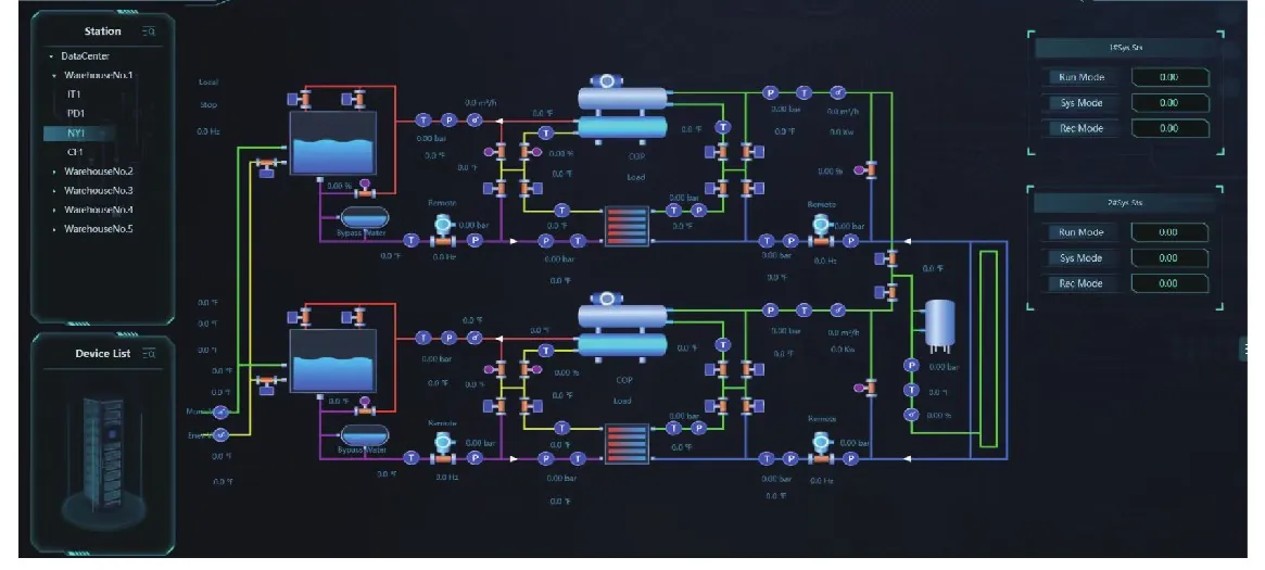
DCIM monitoring platform: live cooling and power schematic.
Monitored systems
- Power: UPS, batteries and distribution equipment
- Cooling: CDU, pumps, valves and coolant status
- Environment: temperature, humidity and air quality
- Security: access control and CCTV
Liquid-cooled blocks, sized to the cluster.
Engineering examples from our design library. Every deployment is engineered to order around its own load, redundancy and climate.
- Rack density 100 kW+
- 2N UPS
- 10-min lithium battery autonomy
- Air-cooled magnetic bearing chiller with free cooling; hybrid air / liquid
- Novec 1230 & VESDA
- Rack density 100 kW+
- 2N UPS
- 10-min lithium battery autonomy
- Water chiller and plate heat exchanger with free cooling; cooling tower heat rejection
- Novec 1230 & VESDA
- 5× dual-40 ft modules
- 30 liquid-cooled racks, 100 kW per rack
- 2N power, 10-minute Li-ion
- Magnetic-bearing chiller + liquid cooling
- Novec 1230 + VESDA
- 1× dual-40 ft module
- 6 liquid-cooled racks, 100 kW per rack
- 2N power, 10-minute Li-ion
- Hybrid cooling, chilled water + free cooling
- Novec 1230 + VESDA
2.0 MW in two IT PODs
18 liquid racks, 2N redundancy for IT and chiller, 10-minute Li-ion backup. From a single module to a scalable multi-megawatt data center; all disciplines are integrated, connected and tested before the module leaves the factory.
Where capacity has to go live fast.
Full data center capability in a transportable form, wherever a conventional data hall is not an option.
AI training data centers
High-density GPU clusters, with rack densities beyond 100 kW per rack.
HPC centers
Scientific and engineering computing with sustained, concentrated heat loads.
Cloud data centers
Hyperscale and enterprise cloud capacity, delivered in phases as demand grows.
Telecom edge facilities
Distributed infrastructure placed close to users, networks and data sources.
Government & smart city
Mission-critical computing in controlled, secure, rapidly deployed facilities.
Containerized builds, delivered and in progress.
Scope in each delivered project: layout design, power and cooling integration, factory build, FAT and delivery.
| Country | Type | IT capacity | Racks | Per rack | UPS | Cooling | Backup | Configuration |
|---|---|---|---|---|---|---|---|---|
| Kazakhstan | Air-cooled containerized | 168 kW | 24 | 7 kW | 2N | N+1 in-row | 20 min VRLA | 3× 40 ft units |
| Iraq | Air-cooled containerized | 120 kW | 20 | 6 kW | 2N | N+1 in-row | 2 h VRLA | 3× 40 ft units |
| Ethiopia | Air-cooled containerized | 40 kW | 8 | 5 kW | 2N | N+1 in-row | 60 min VRLA | 1× 40 ft module |
| Kazakhstan | Air-cooled containerized | 45 kW | 9 | 5 kW | N | N+1 in-row | 10 min VRLA | 3 modules, 15 kW each |
7.2 MW liquid-cooled containerized
6× 1.2 MW B200/B300 GPU cluster blocks: 12 IT PODs, 14 electrical PODs and 4 auxiliary PODs, 72 liquid racks, 2N for IT and chillers, 10-minute Li-ion backup.
40 MW liquid-cooled containerized
16× 2.5 MW compute blocks at 50 kW per rack, N+1 power and N+1 cooling.
Engineering drawings, discipline by discipline
For the Ethiopia containerized project: equipment and floor layout, container structure, foundation, grounding and opening drawings; distribution architecture and system diagrams; HVAC layouts; monitoring system diagrams and wiring; fire protection flowchart, cabinet-type FM200 equipment and fire system layout.
The same building blocks, at every scale.
Every system is integrated and tested at our Hangzhou manufacturing base, an audited supplier to Schneider Electric. Data center overview →
Micro-modular & edge
Warrior, Wizard and WT-MMDC: one cabinet to 48-cabinet modules.
View →Data centerAI POD & liquid cooling (CDU)
Prefabricated overhead pods to 250 kW per rack; rack CDUs from 30 to 150 kW.
View →Data centerRacks & DCIM
LS Series 42U / 47U server racks and the monitoring platform across every system.
View →Send IT load, rack count, kW per rack, climate and power supply.
We return a matched configuration with layout and lead time.