 Optical network solutions
AI POD and rack-levelliquid cooling.
The busway, liquid cooling piping, cable trays and aisle containment that normally take months to build above the racks, prefabricated as one steel-framed pod and lifted into place. With WT-CDU rack-mounted units, liquid cooling deploys one rack at a time.
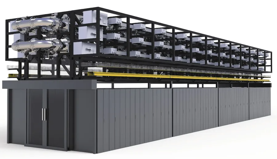
Move the work above the rack into the factory.
Installing the frame that supports IT, power and cooling often takes months, with schedule delays, complex multi-trade coordination and material waste of 10–15%. What remains on site with the AI POD is lifting, connection and acceptance testing.
Faster deployment
Factory prefabrication replaces months of overhead on-site construction.
Lower capex
Reduced by at least 15% versus conventional on-site build.
More usable space
Modular design practice unlocks up to 30% of space.
One purchase
One integrated system from one supplier, instead of sourcing busway, piping and containment separately.
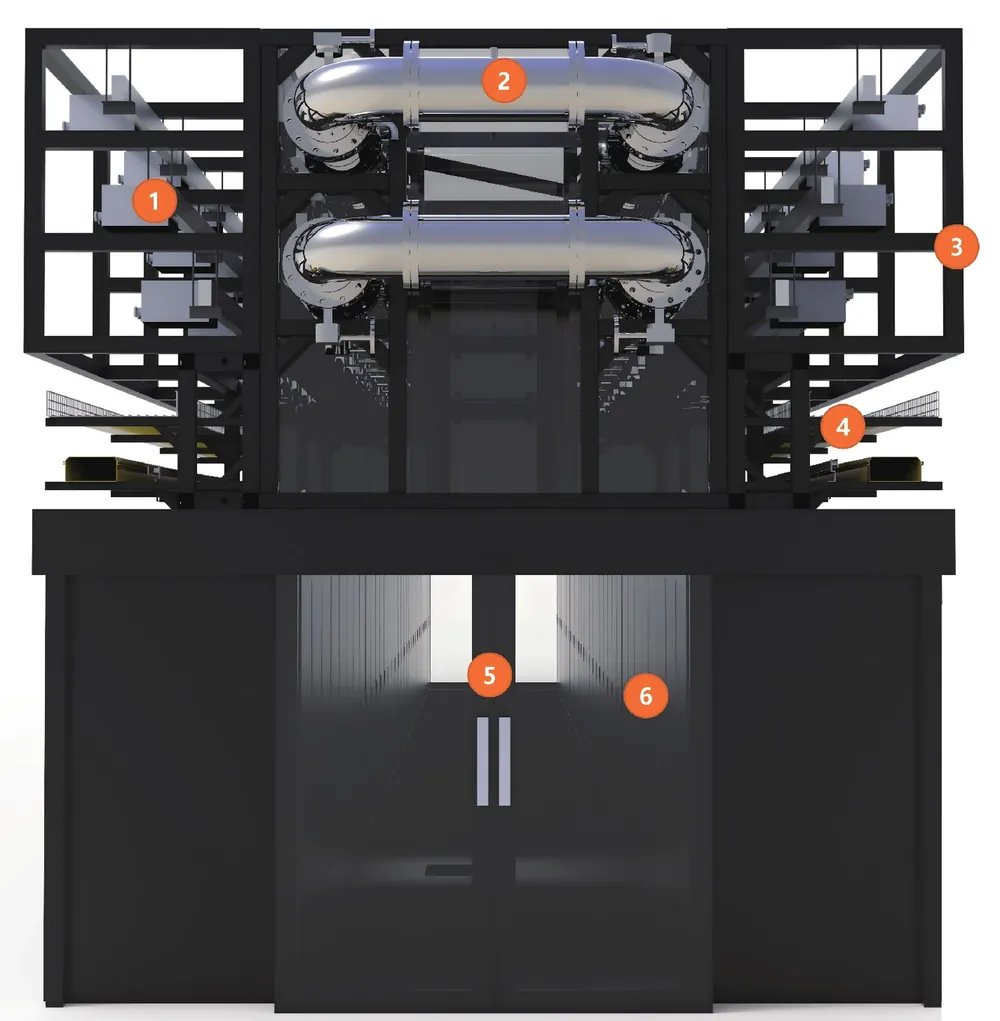
System architecture
The pod frame sits above the rack row and carries every overhead service. The contained aisle below keeps its double glass door and rack line unchanged.
- 1 Intelligent busway system
- 2 Technical water loop
- 3 Steel framework
- 4 Cable tray
- 5 Double glass door
- 6 Racks
At a glance.
Pod length, busway architecture (2Bus / 4Bus / cable), cooling layout and CDU interface are engineered per project.
| Parameter | Specification |
|---|---|
| Racks per pod | 42–46 rack spaces (600–1200 mm racks) |
| Rack power density | Up to 250 kW per rack |
| Unit capacity | 2.2–8.0 MW per pod |
| Busway | Up to 4000A (2Bus) / 6300A (4Bus), up to 600V, 3Ph + PE |
| Liquid cooling | Up to 5 MW thermal capacity per pod; DN250 main header; 250+ kW per branch |
| Frame load capacity | Up to 1360 kg/m total unit weight capacity (4Bus) |
| Seismic design | Up to Zone 4 |
| Deployment | Factory pre-integrated; section-by-section delivery; lift-and-set on site |
Subsystem detail
| Subsystem | Parameter | Value |
|---|---|---|
| Structural frame | Total unit weight capacity | 750 / 915 / 885 lbs/ft (1115 / 1360 / 1315 kg/m) for 2Bus / 4Bus / Cable |
| Infrastructure weight capacity | 465 / 605 / 555 lbs/ft (690 / 900 / 825 kg/m) | |
| Load per unit | Up to approximately 29,000 lbs of data center infrastructure | |
| Mounting | Post-mounted or floor-standing; suspended possible; post height 8 ft (2.4 m) | |
| Seismic | Designs up to Zone 4, pre-designed for 95% of global coverage | |
| Busway | Type / busbars | Enclosed channel track busway; 4–8 busbars per row, each run independent |
| Redundancy | N or 2N (2Bus); N, 2N, 4N/3 (4Bus); 3Ph + PE | |
| Tap boxes | Up to 4 pcs (4Bus) per rack slot, up to 200A each; finger-safe and hot-swappable | |
| Maintainable power density | 334 kW concurrently maintainable (standard); up to 345 kW (4Bus) | |
| Liquid cooling (TCS) | System / header | Stainless steel Technology Cooling System; main header up to 10 in (DN250), ring or straight section |
| Rack branch | 1/2-inch interlocking ball valve quick-connect at 600 mm increments; rack isolation and energy control valves | |
| Operating parameters | 90:10 liquid-to-air; 1.5 LPM/kW; 8 ft/sec; PG25 / EG25 / deionized water | |
| CDU interface | Engineered to order (ETO) per project | |
| Hot aisle containment | Construction | Polycarbonate paneling with sliding doors; adjustable filler panels |
| Fit / width / rating | Rack height up to 52U; hot aisle 6 ft (1.8 m); Category C standard, D and E by request | |
| Monitoring & lighting | Protocols / points | Modbus, BACnet, TCP, PLC; pressure, flow, temperature, leak detection |
| Lighting / trays | 40FC, 80CRI, 4000K; up to 3 tiers of cable tray per row |
Three power architectures.
Choose by redundancy topology and how much the row will change over its life.
- N or 2N redundancy
- Up to 600V, 3Ph + PE
- 1115 kg/m total unit weight capacity
- Mixes storage, networking and liquid-cooled AI compute in one row
- N, 2N or 4N/3 redundancy
- Up to 4 tap boxes per rack slot, 200A each
- Up to 345 kW concurrently maintainable
- 1360 kg/m total unit weight capacity
- 2.2–8.0 MW depending on voltage and redundancy
- Protection centralized upstream in RPP, PDU or switchgear
- Top of rack or back of rack connection
- For static, fixed-load, ultra-dense deployments
Liquid cooling, one rack at a time.
Localized, high-density liquid cooling delivered directly to the rack for AI servers, intelligent computing clusters and HPC. Available in 4U, 6U, 8U and 12U form factors, for individual cabinets or cabinet rows.
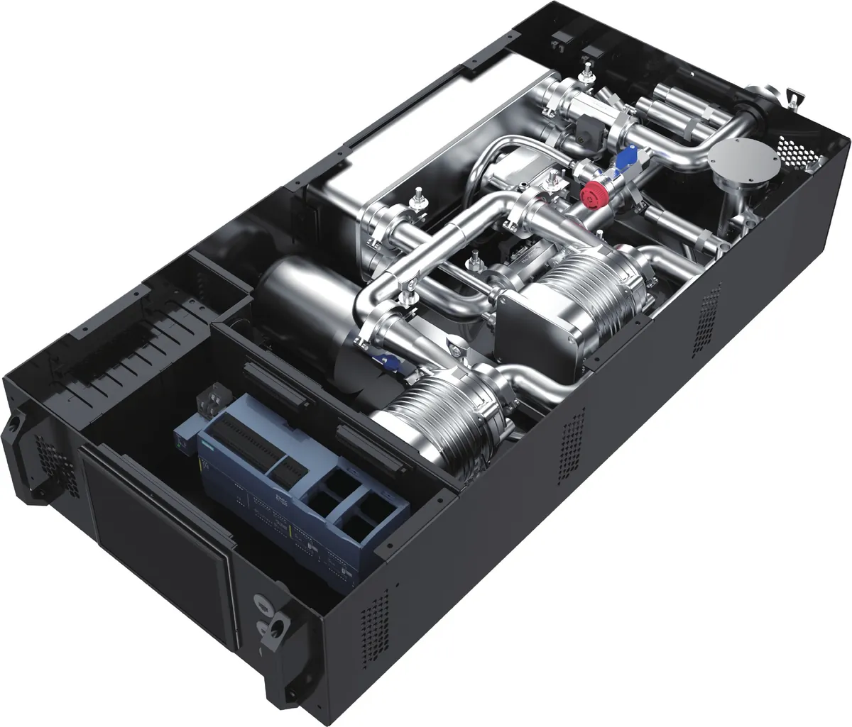
Features
- Space-optimized: rack-level integration, no dedicated mechanical space
- Localized distribution: short piping routes; faults contained at the rack
- Modular & scalable: add cooling capacity alongside new cabinets
- Carrier-grade reliability: N+N redundant pumps, dual power feeds, leak detection, anti-condensation control
- Fluid integrity: high-purity stainless steel piping and precision filtration
- Smart & connected: Modbus, TCP/IP and UDP for DCIM and BMS integration
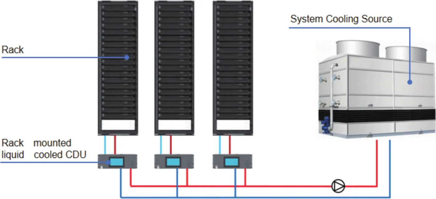
Each rack carries its own CDU; the primary loop runs to the system cooling source.
Five models, 30 to 150 kW.
Specifications are subject to project configuration. Model, interface and coolant are matched to the server and the site.
| Parameter | Unit | WT-CDU-Y30 | WT-CDU-Y60 | WT-CDU-Y80 | WT-CDU-Y100 | WT-CDU-Y150 |
|---|---|---|---|---|---|---|
| Rated heat transfer capacity | kW | 30 | 60 | 80 | 100 | 150 |
| Primary: circulating medium | / | Cooling water | ||||
| Primary: design inlet / outlet temperature | °C | 35/45 | ||||
| Primary: circulating flow rate | m³/h | 2.8 | 5.6 | 7.5 | 9.3 | 14 |
| Primary: interface | mm | DN25 | DN32 | DN40 | DN40 | DN50 |
| Primary: water pressure drop | kPa | ≤80 | ||||
| Secondary: circulating medium | / | Demineralized water / 25% propylene glycol (PG25) | ||||
| Secondary: design inlet / outlet temperature | °C | 50/40 | ||||
| Secondary: inlet / outlet temperature range | °C | 20-50 | ||||
| Secondary: flow rate | m³/h | 2.8 | 5.6 | 7.5 | 9.3 | 14 |
| Secondary: interface | mm | DN25 | DN32 | DN40 | DN40 | DN50 |
| Secondary: total head | m | 15 | ||||
| Rated electric power | kW | 0.7 | 1.5 | 1.8 | 2.2 | 3 |
| Weight in operation | kg | 70 | 85 | 96 | 116 | 190 |
| Maximum working pressure | Bar | 5 | ||||
| Dimensions | mm | 447 × 178 × 851 | 447 × 267 × 920 | |||
Sized for accelerated compute.
The AI POD serves full rows at hyperscale density; the WT-CDU brings liquid cooling to individual racks.
AI infrastructure
AI server deployments and intelligent computing clusters.
Hyperscale & colocation
Indoor hyperscale data centers and colocation facilities.
HPC & research
High-performance computing, research and supercomputing centers.
Cloud, edge & enterprise
Cloud and edge data centers and enterprise data centers adding liquid cooling.
Liquid-cooled builds in progress.
Containerized liquid-cooled data centers currently in progress.
7.2 MW liquid-cooled containerized
6× 1.2 MW B200/B300 GPU cluster blocks: 12 IT PODs, 14 electrical PODs and 4 auxiliary PODs, 72 liquid racks, 2N for IT and chillers, 10-minute Li-ion backup.
40 MW liquid-cooled containerized
16× 2.5 MW compute blocks at 50 kW per rack, N+1 power and N+1 cooling.
The same building blocks, at every scale.
Every system is integrated and tested at our Hangzhou manufacturing base, an audited supplier to Schneider Electric. Data center overview →
Containerized & liquid-cooled
IT hall, power and cooling plant in factory-built container modules, 100 kW to 10 MW+.
View →Data centerMicro-modular & edge
Warrior, Wizard and WT-MMDC: one cabinet to 48-cabinet modules.
View →Data centerRacks & DCIM
LS Series 42U / 47U server racks and the monitoring platform across every system.
View →Send IT load, rack count, kW per rack, climate and power supply.
We return a matched configuration with layout and lead time.