 Optical network solutions
DWDM solutions,engineered to the link.
Upgrade an existing network, expand metro, backbone and DCI capacity, or protect a 400G interconnect. Each solution starts from one link, with reuse decisions, validation and rollback agreed before cutover.
More capacity from the fiber you already have.
For metro, backbone and data center interconnect projects. Every existing asset receives a reuse, replacement or addition decision, and a recorded engineering decision defines the final reuse scope.
Capacity on an installed route
New services must run over existing fiber, hosts and optical layer, without an uncontrolled change to live traffic.
Reuse first, add where needed
Host interface and optics adaptation into a WDM system at each site, over the existing fiber under review.
Matched to the path
- Passive CWDM / DWDM, MUX48 / MUX96
- WTNS8600-OLS open line system
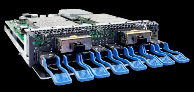
- WTN8600-DCI and WTNS8600 platforms
National ISP backbone
100G services added alongside existing 10G DWDM traffic: 4× 100G over 500 km, with amplification and dispersion compensation.
Existing and target network
Illustrative architecture for a link under review.
Reuse and additions
| Existing asset | Before reuse | Add or change when needed |
|---|---|---|
| Fiber route | Route survey and measured optical loss | Wavelength or line equipment for the selected link |
| Hosts and ports | Host, software, port mode, FEC and power support | Optics or interfaces that pass evaluation |
| Optics and line cards | Channel plan, power limits and supported profiles | Adaptation, amplification or protection per design |
| Site and operations | Rack, power, cooling and management access | Supporting hardware and operating procedures |
Candidate upgrade paths
| Path | Potential fit | Decision checks |
|---|---|---|
| Optics with passive WDM | Wavelength-compatible hosts and a suitable fiber path | Host acceptance, channel plan, optical budget and expansion |
| Host coherent optics with a line system | A qualified coherent host interface with line engineering | Host profiles, optical mode, FEC, power and optical margins |
| Transport or DCI platform | Client adaptation or aggregation through selected equipment | Service mapping, protection, monitoring and site constraints |
Capabilities depend on the specific product, configuration and link design.
Validation, cutover and rollback
Baseline
Save inventory, settings and optical readings. Agree test criteria and the restore procedure.
Pilot validation
Test the host and link. Record traffic, alarms and optical results.
Controlled cutover
Use the change window. Move agreed services and monitor both directions.
Acceptance
Test included protection, observe for the agreed period, close issues and confirm acceptance.
Rollback gate: if traffic or test results cross the agreed limits, the change stops and the approved baseline is restored, with service recovery verified and logs captured before any retry. The customer change owner approves each gate.
Turn up capacity without skipping link engineering.
For new 10G, 25G, 100G or 400G ports and interconnects, metro and DCI projects that need optics or CWDM / DWDM components for a defined link, and turn-ups held back by mixed SKUs and open technical questions.
Growth on a deadline
Bandwidth demand outpaces the transport layer, and quotation or turn-up waits on unconfirmed reach, wavelength plan and budget.
Sized by distance
- ≤10 / 30 km: O-band 100G, up to 12 × 100G
- Metro and backbone: C-band coherent 100G–400G with ROADM and OLA
- Long haul: 800G, 32 waves over 480 km
One card family
- P422 to P624 muxponders; P716 for 800G
- OA / OTA / OLA, WSS ROADM, OLP
- WTNS8600P for 1RU point-to-point links
Delivered networks
- 29 DWDM systems, 40-channel protected ring, 1,116 km longest route
- Metro OTN rings for a public security network
- 26 bank branches on a single fiber
Reach tiers at 800G
P716 muxponders with flexible ROADM or 32 / 40-channel Mux / Demux at each end.
How the evaluation works
Map
The service, topology, host equipment and acceptance date for one link or BOM.
Validate
Reach, wavelength plan, link budget, FEC and, where relevant, dispersion and amplification.
Return
A scoped option with sample, import, documentation and RMA responsibilities confirmed.
You provide
- Topology and deployment location
- Host equipment and software
- Speed, reach, fiber and connector
- Optical budget and wavelength plan
- Quantity, required date and local rules
We return
- Candidate BOM with exclusions: optics, line system, protection, NMS
- Pilot and acceptance plan with schedule
- Delivery, documentation and RMA split
Long-reach and DWDM performance depends on full link design; product supply alone is not a guarantee of end-to-end link performance.
4× 100GE between two sites, on two protected routes.
A lightweight DCI for point-to-point requirements: a cost-effective alternative to a fuller telecom DCI platform, managed together with traditional WDM equipment. For larger growth, more spans or broader network functions, our enhanced DCI series takes over.
Protect a 400G interconnect
Two sites, two fiber routes of 32 dB attenuation each on G.652 single-mode fiber, 400 Gb/s per direction from day one.
One wave, two routes
One coherent 400G wavelength carries 4× 100GE; 1+1 OLP switches between working and protection routes, each with its own BA / PA.
2U, 8 slots per site
- 400G muxponder + CFP2
- 4-channel Mux / Demux, 1+1 OLP
- Dual BA / PA, 8-port OTDR, EMS
Room to grow
- C21 active at 400G; C22–C24 held
- Site A 6 / 8 slots used, Site B 5 / 8
- One EMS for DCI and WDM
Protected line architecture
Per site, mirrored at Site A and Site B. Both routes dual fiber; physical route diversity and measured loss confirmed on site.
Site A · 2U chassis
6 of 8 slots used; one physical OTDR card; 2 spare.
Muxponder4CH
Mux / Demux1+1
OLPBA / PA
WorkingBA / PA
ProtectionOTDRSpareSpare
Site B · 2U chassis
5 of 8 slots used; no physical OTDR card; 3 spare.
Muxponder4CH
Mux / Demux1+1
OLPBA / PA
WorkingBA / PA
ProtectionSpareSpareSpare
Chassis: 88 × 446 × 450 mm, 19-inch 2U; 1+1 redundant power supplies; 2+1 redundant fans; LCD maintenance display, console port, Ethernet and 2 SFP management ports. Functional slot allocation; physical positions confirmed at engineering.
Equipment summary
| Equipment | Site A | Site B | Total | Key specification |
|---|---|---|---|---|
| 2U DCI chassis | 1 | 1 | 2 | 19-inch, 8 slots; main control and management interface boards; LCD; 2+1 fans; 1+1 power supplies |
| 400G muxponder | 1 | 1 | 2 | 4× QSFP28 client ports; 1× CFP2 line port; carries 4× 100GE; 1 slot |
| 4-channel DWDM Mux / Demux | 1 | 1 | 2 | 100 GHz spacing; main-line input / output power monitoring; expansion ports; LC; 1 slot |
| 1+1 optical line protection | 1 | 1 | 2 | Optical route protection; LC; 1 slot |
| 8-port OTDR | 1 | 0 | 1 | 8 monitoring interfaces; stated dynamic range 33 dB; 1 slot |
| Dual BA / PA amplifier | 2 | 2 | 4 | Maximum output +20 dBm; BA gain 17 dB; PA gain 25 dB; VOA; MON; OTDR access; LC; 1 slot |
| 400G coherent CFP2 | 1 | 1 | 2 | Tunable DWDM, 190.69375–196.65625 THz; LC |
| 100G QSFP28 SR4 | 4 | 4 | 8 | 850 nm; MPO; up to 100 m on suitable multimode fiber |
| 1.25G DWDM management SFP | 1 | 1 | 2 | Stated reach 80 km; LC |
| Network management software | 1 | 0 | 1 | Browser / server EMS: fault, performance, configuration and security |
Additional cards or optics are reviewed against spare slots, power, cooling and optical budget. Peer optics, patch cords, server and switch hardware and installation are not included in this configuration.
Optical engineering and acceptance
- Full optical loss: 32 dB fiber attenuation plus Mux / Demux, OLP, connectors, splices, taps and engineering margin.
- Receive power and OSNR: verified for both directions, current and future loading, coherent mode and FEC threshold.
- Amplifiers: input / output limits, per-channel power, noise figure, gain and VOA settings confirmed.
- OTDR: monitoring wavelength, pulse settings, dead zones and port mapping confirmed against the 32 dB route.
- Management and client optics: 1.25G management budget and wavelength; SR4 cabling, MPO polarity and peer ports.
- Protection tests: route diversity, OLP switching thresholds and time, and working / protection failures in both directions.
One topology and one device list.
That is enough for a scoped technical discussion. We return a candidate path with its reuse assumptions, equipment scope and validation plan.
You share
- Current topology, fiber route and measured loss records
- Host models, software, ports and installed optics
- Required services, growth, protection and the available change window
We return
- Candidate upgrade path with reuse assumptions
- Reuse and replacement matrix with a draft equipment scope
- Validation plan, cutover steps and rollback responsibilities
Share one link for a scoped review.
Route, span loss, existing channels, host models and the services you need to carry.